1. When replacing the control module of new panoramic camera system, this function needs to be executed;
2. This function needs to be executed when replacing the front camera, passenger camera, cab camera and rear camera;
3. This function needs to be executed when the front camera, passenger camera, cab camera and rear camera are disassembled;
4. There are relevant fault codes, and this function needs to be executed;
1. The vehicle is parked on a flat ground. There is no load on the vehicle and the steering wheel is returned to the straight line;
2. All doors of the vehicle are closed;
3. normal tire pressure;
4. The lenses of the front camera, passenger camera, cab camera and rear camera are clean and unobstructed;
5. The light on the field is bright enough, and there are no reflective or flashing objects around the target.
VIN code: LGBF5ADE03DR201347
1. Turn on the ignition switch of the car, select the NISSAN model software, V44.70 and above, and enter the following menu interface.
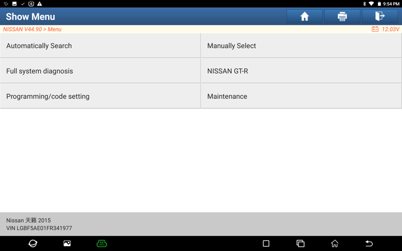
2. Select [Automatically Search], and display the model information after entering.
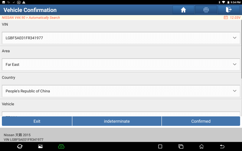
3. Select [Confirmed], and enter the following menu interface.
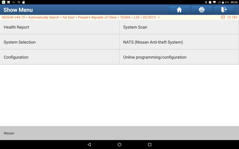
4. Select [System Selection], and display the system of auto model.
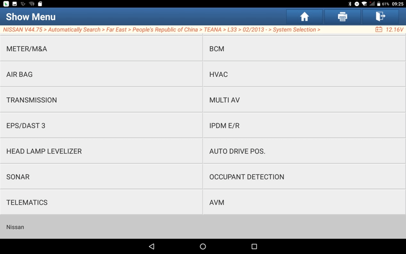
5. Select [AVM] to enter the system.
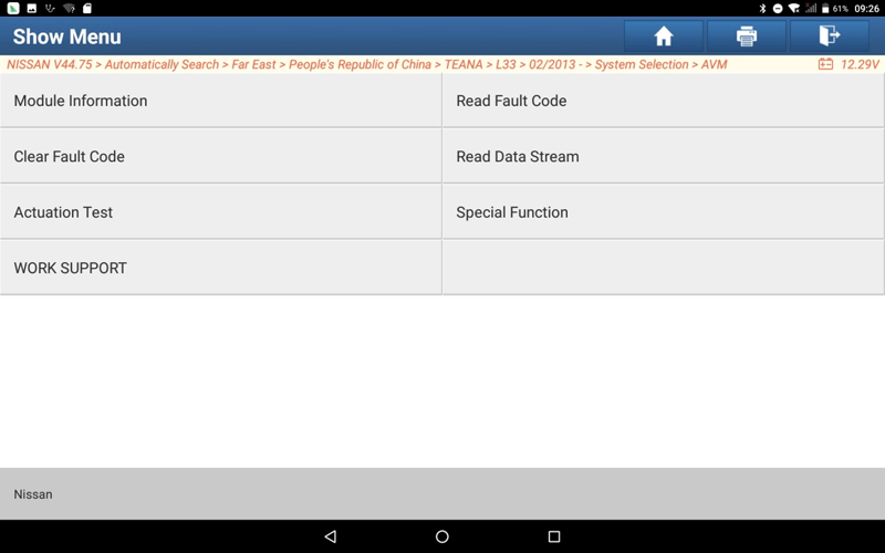
6. Select [Read Fault Code], there is a fault code: U1304-00 camera image correction, U1308-00 rear camera correction judgment, and camera calibration is required. Enter the following function menu interface.
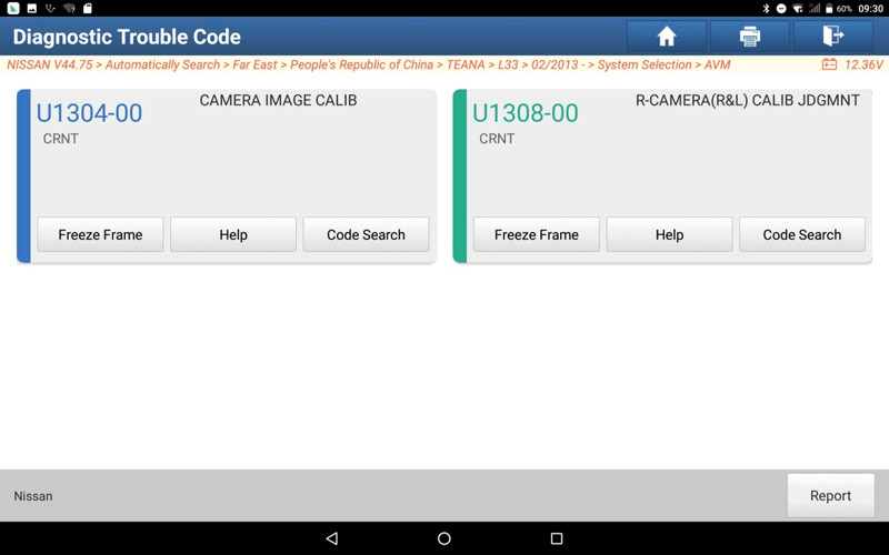
7. Exit the function interface of reading fault codes, select [Special Function], and enter the following menu interface.
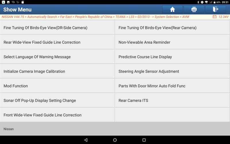
8. Select [Rear Camera ITS], enter the following interface.
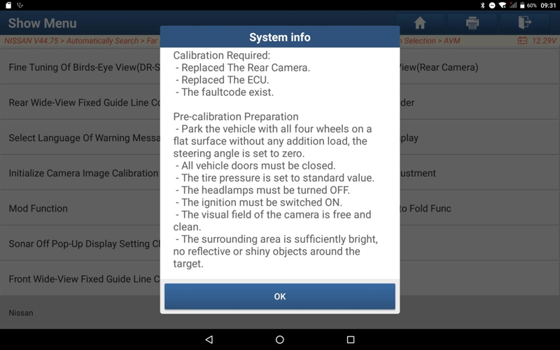
9. Click [Ok], and proceed to the next step.
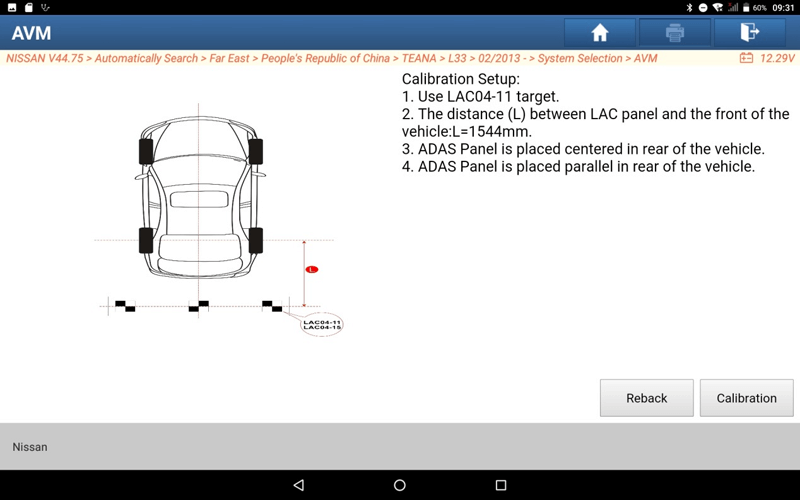
10. According to the prompt information, place the LAC04-11 target:
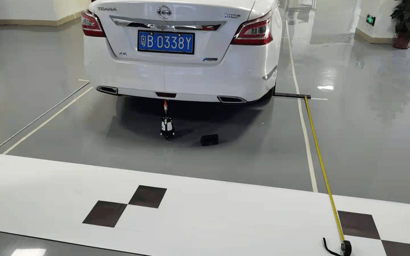
10-1. Determine the centerline of the vehicle using plumb bobs and laser instruments, and align the center of the LAC04-11 target, as shown in the figure:
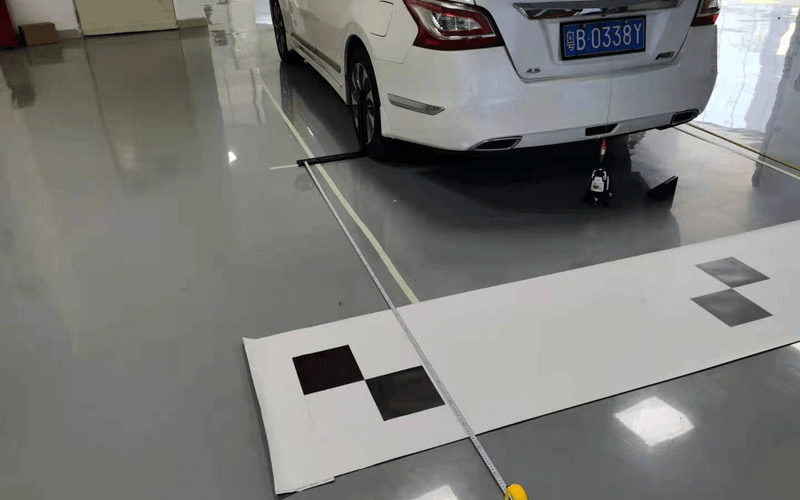
10-2. Using an L-bracket and tape measure, determine the distance from the LAC04-11 target to the center of the rear wheel, as shown below:
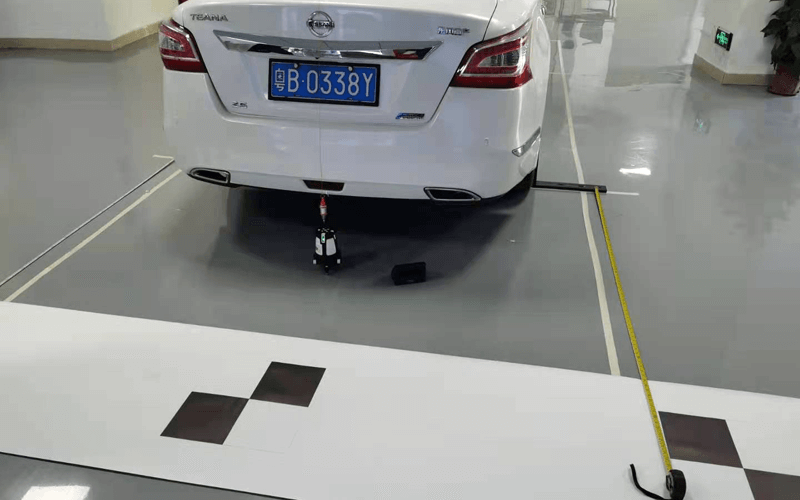
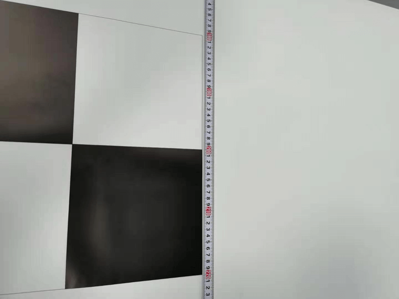
10-3. Set up the LAC04-11 target, remove the tape measure, plumb weight, laser, reflector and other tools, as shown in the picture:
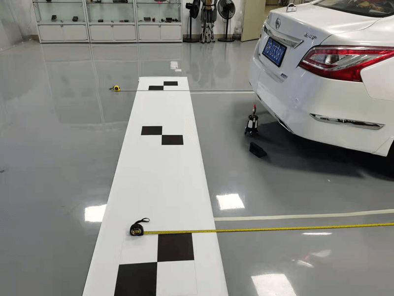
11. Place the target, select [Calibration], and start the camera calibration.
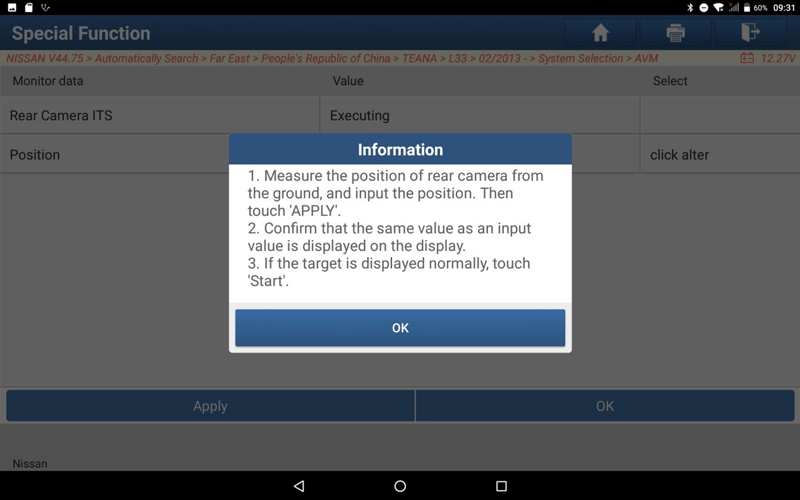
12. According to the prompt information, measure the height of the rear camera, and then enter the value of the camera height.
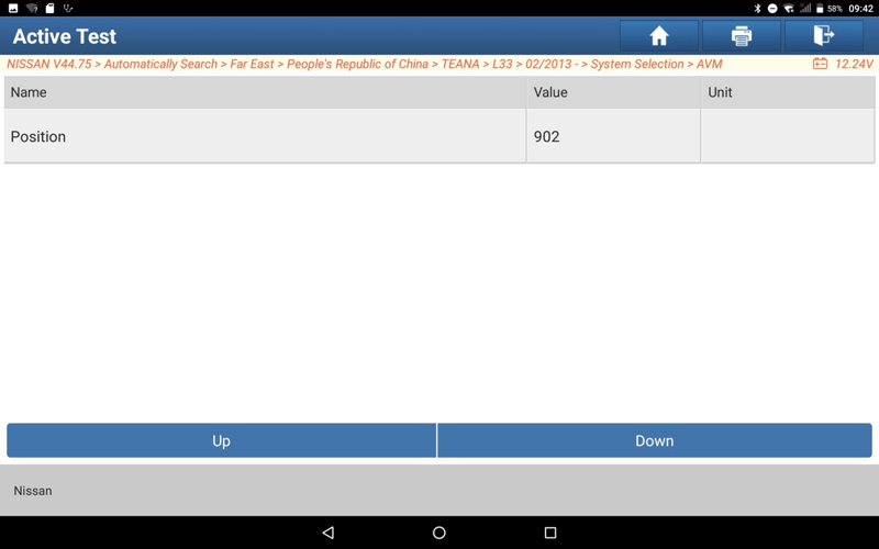
13. Modify the camera height value.
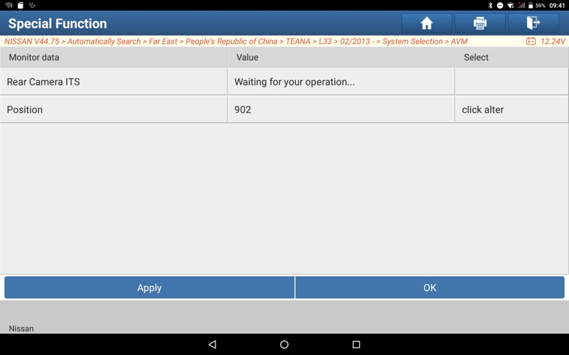
14. Select [OK], as shown below:
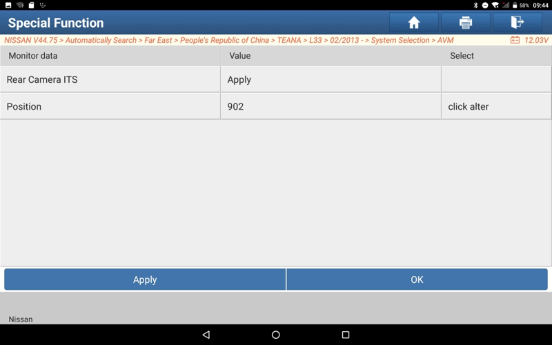
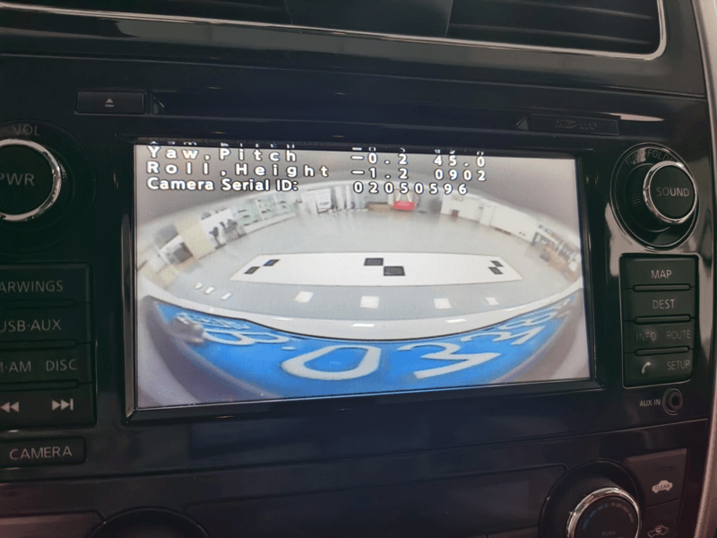
15. Select [OK], as shown below:
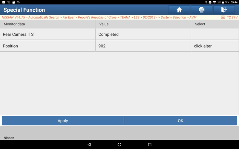
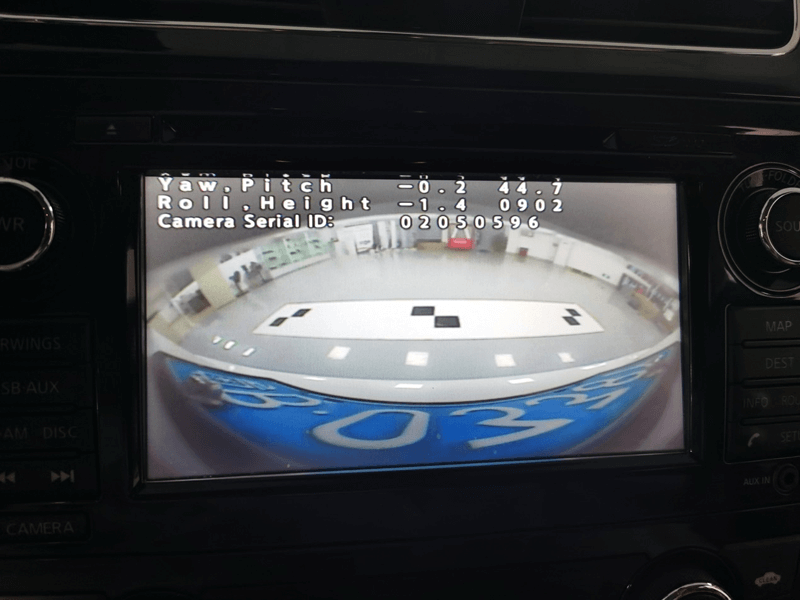
16. Rear camera ITS calibration completed.
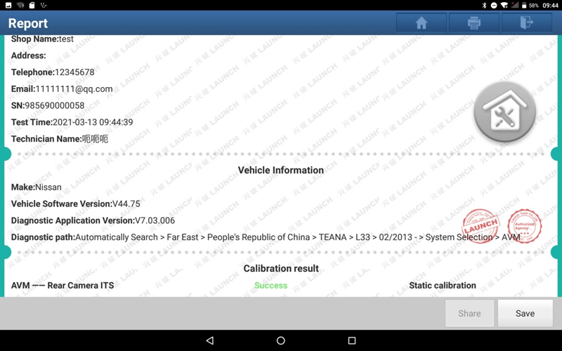
17. Return to the [Special Function] interface, ready to execute the camera calibration function.
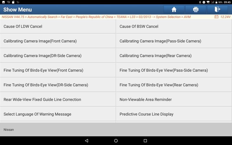
18. Select [Calibration Camera Image (Front Camera)].
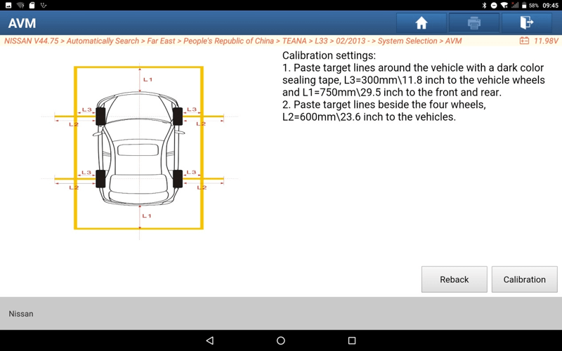
19. Follow the prompts and paste the marking lines. as the picture shows:
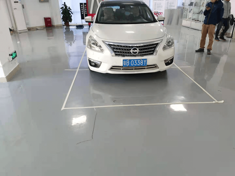
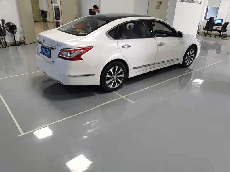
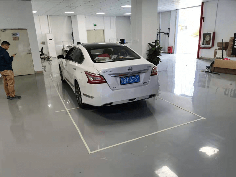
20. Paste the marking line, select [ok], and perform camera calibration (front camera) calibration.
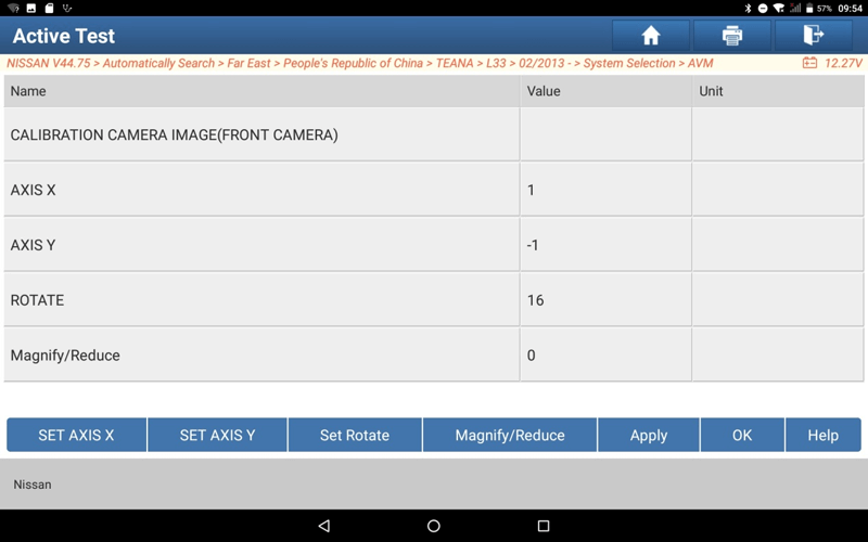
21. Modify the three values of X-axis, Y-axis and rotation, and click Apply, so that the red line on the central control screen coincides with the target. As shown in the figure:
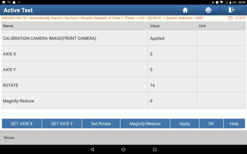
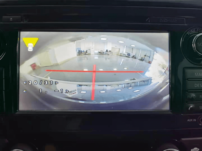
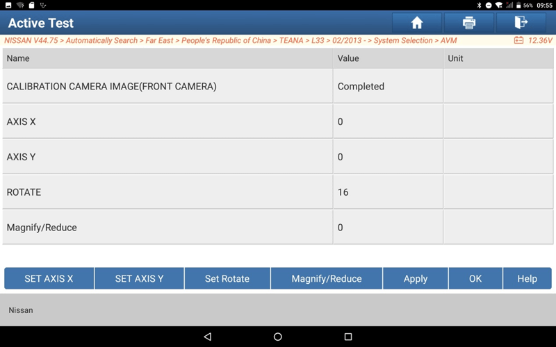
22. Select the [ok] to complete the front camera calibration.
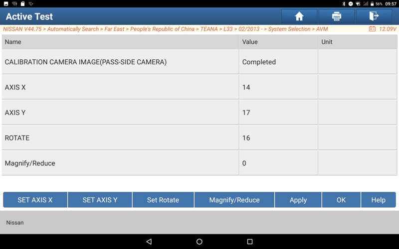
23. Select [Calibration Camera Image (Pass-Side Camera)], modify the three values of X-axis, Y-axis, and rotation, and click [Apply], so that the red line on the central control screen coincides with the target.
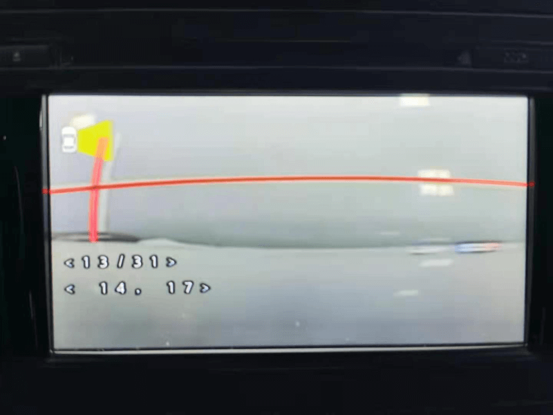
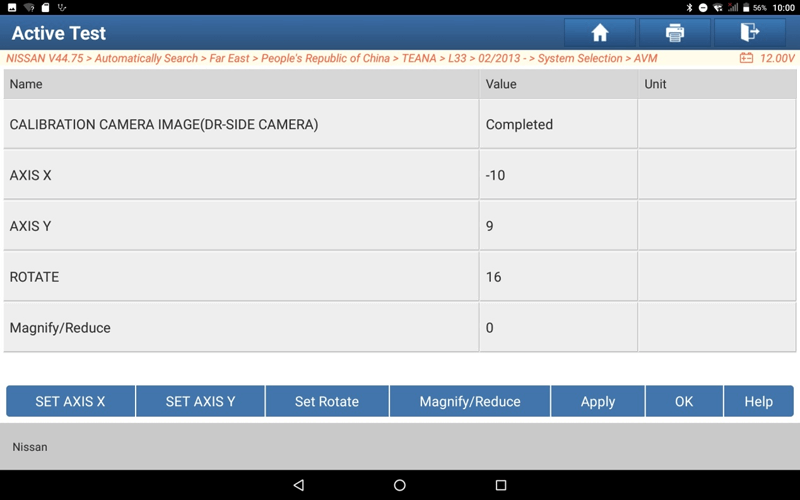
24. Select [Calibration Camera Image (DR-Side Camera)], modify the three values of X-axis, Y-axis, and rotation, and click [Apply], so that the red line on the central control screen coincides with the target.
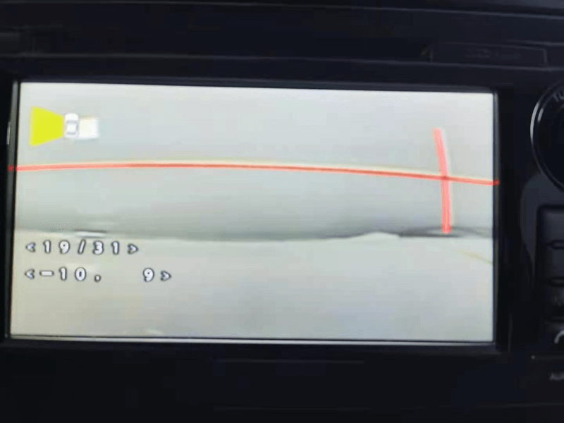
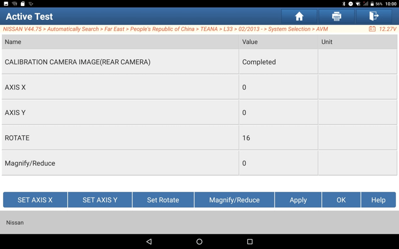
25. Select [Calibration Camera Image (Rear Camera)], modify the three values of X-axis, Y-axis, and rotation, and click [Apply], so that the red line on the central control screen coincides with the target.
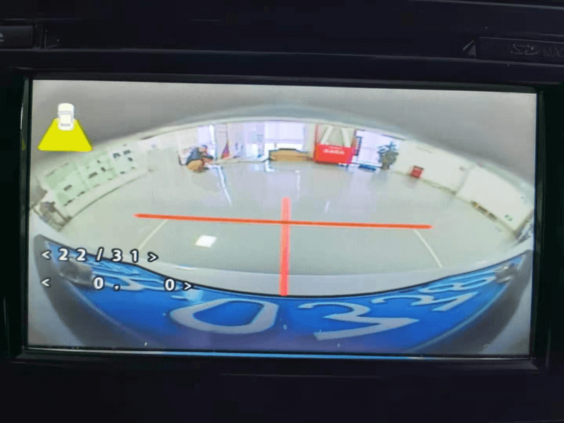
26. Select [Fine Tuning of Birds-Eye View (Front Camera)], modify the three values of X-axis, Y-axis, and rotation, and click [Apply], so that the red line on the central control screen coincides with the target.
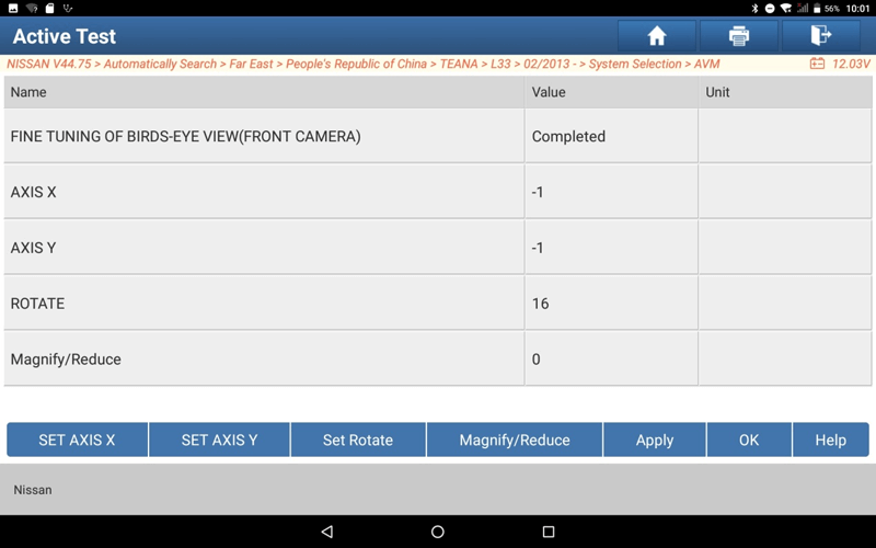
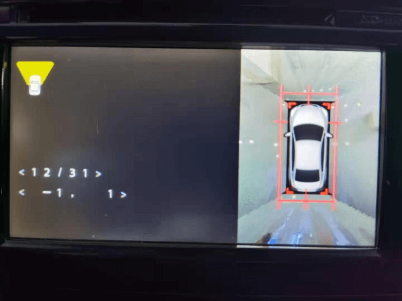
27. Select [Fine Tuning of Birds-Eye View (Pass-Side Camera)], modify the three values of X-axis, Y-axis, and rotation, and click [Apply], so that the red line on the central control screen coincides with the target.
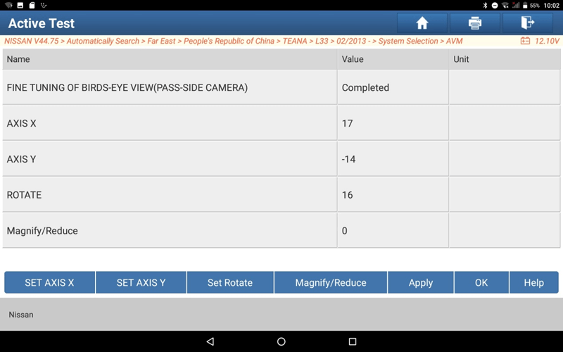
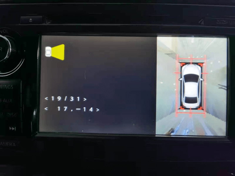
28. Select [Fine Tuning of Birds-Eye View (DR-Side Camera)], modify the three values of X-axis, Y-axis, and rotation, and click [Apply], so that the red line on the central control screen coincides with the target.
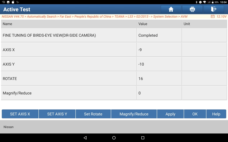
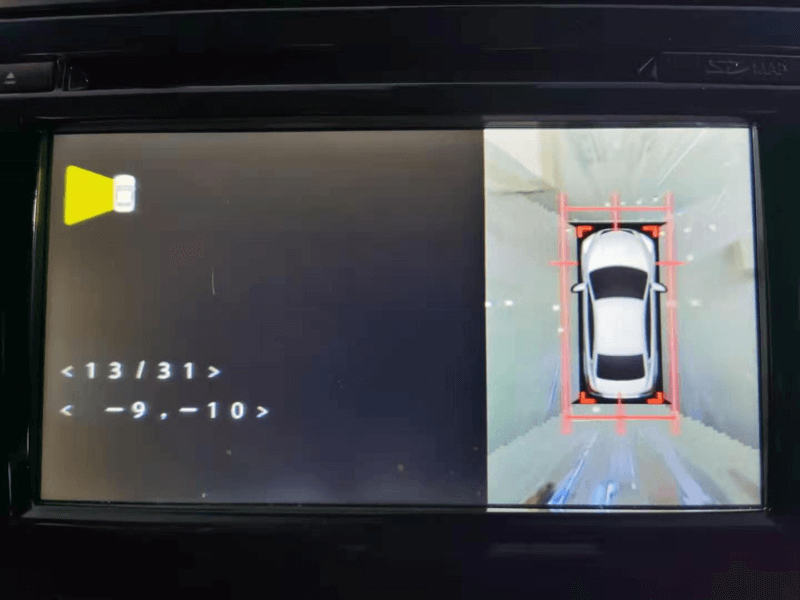
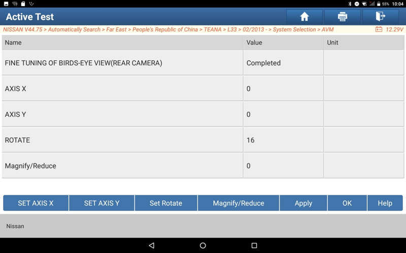
29. Select [Fine Tuning of Birds-Eye View (Rear Camera)], modify the three values of X-axis, Y-axis, and rotation, and click [Apply], so that the red line on the central control screen coincides with the target.
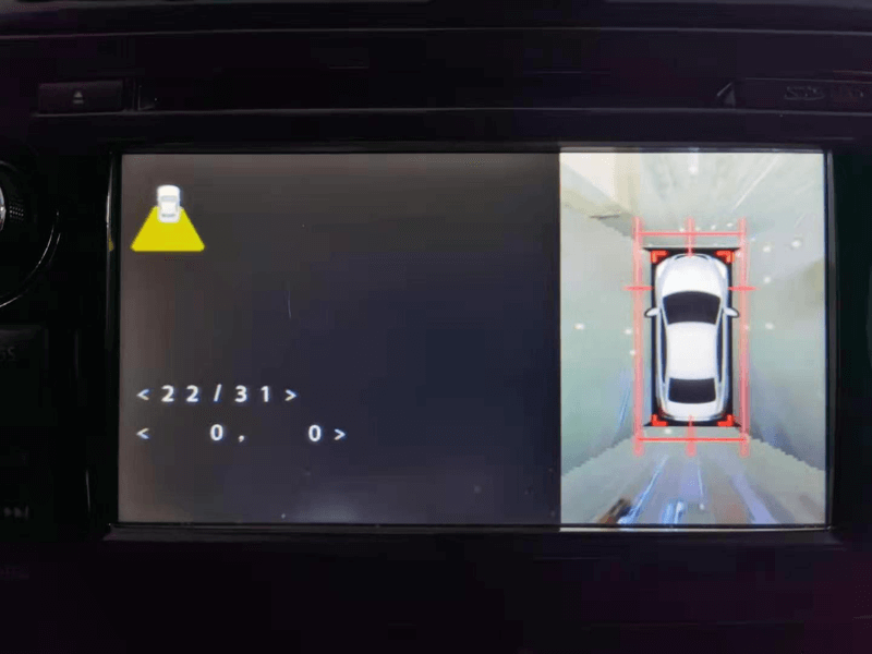
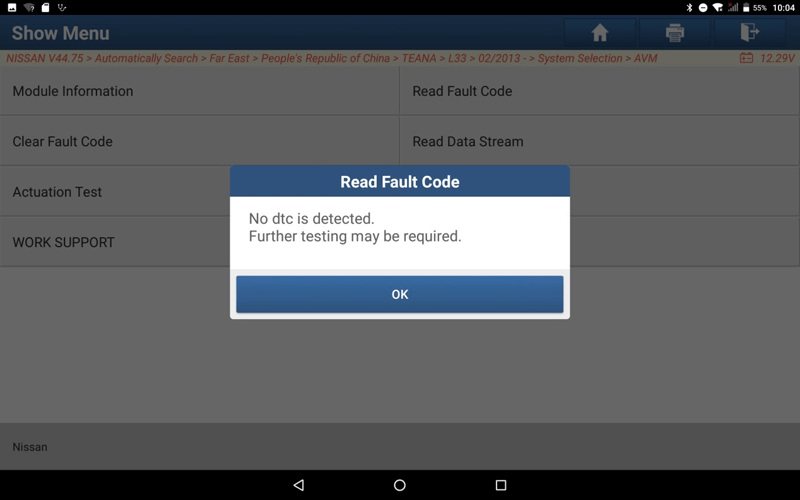
30. The camera calibration is completed, clear the fault code, and check whether there is still a fault.
Return