Background
The vehicle has the following failure records (no or wrong basic settings/adaptation)
(1) D00008 – Calibration
Vehicle parts are overhauled and replaced as follows:
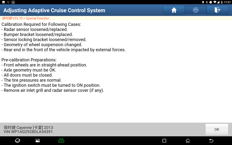
(1) Radar sensor is loose or replaced.
(2) Loose bumper bracket or replace.
(3) Sensor locking bracket is loose or removed.
(4) Wheel suspension geometry changes.
(5) The rear end inside the front of the vehicle is impacted by an external force.
(1) Turn on the car ignition switch.
(2) Radar sensor is loose or replaced.
(3) Loose bumper bracket or replace.
(4) Sensor locking bracket is loose or removed.
(5) Wheel suspension geometry changes.
(6) The rear end inside the front of the vehicle is impacted by an external force.
Porsche Cayenne 92A 2015
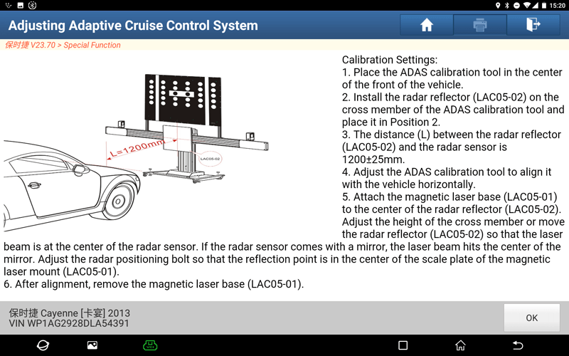
(1) Place the ADAS calibration device in the center of the front of the vehicle.
(2) Install the radar reflector (LAC05-02) on the beam of the ADAS calibration equipment and place it in position 2.
(3) The distance between the radar reflector (LAC05-02) and the radar sensor is L=1200±25mm.
(4) Adjust the ADAS calibration equipment to align horizontally with the vehicle.
(5) Attach the magnetic laser mount (LAC05-01) to the center of the radar reflector (LAC05-02), adjust the height of the beam or move the position of the radar reflector (LAC05-02), so that the laser point is located at the center of the radar sensor; If the radar sensor is equipped with a reflector, the laser light hits the center of the reflector, and the radar positioning bolt is adjusted so that the reflection point is located in the center of the scale plate of the magnetic laser seat (LAC05-01).
(6) After the position is aligned, remove the magnetic laser mount (LAC05-01).
1. The diagnostic tool starts communicating with the VCI and reads the VIN.
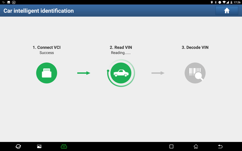
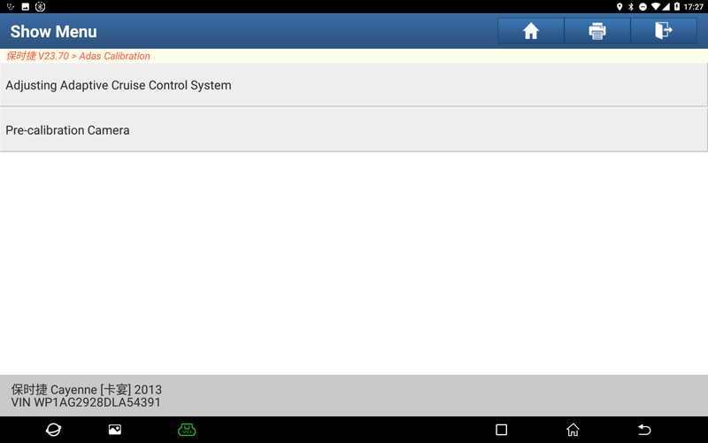
2. After the VIN is resolved successfully, the system will automatically enter the ADAS function selection interface. Here we select the “Adjusting Adaptive Cruise Control System” function.
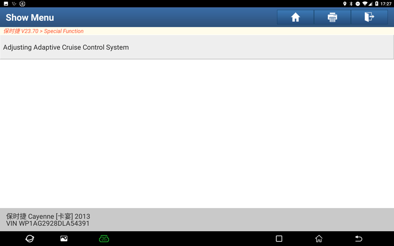
3. Click "Adjusting Adaptive Cruise Control System" to enter the Adjusting Adaptive Cruise Control System function.
4. Follow the instructions and click "OK" to continue.
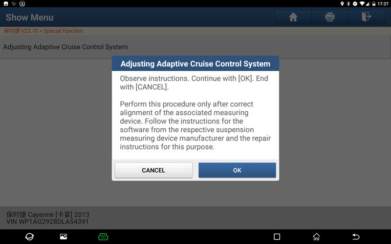
5. Carefully read the calibration operation requirements, and confirm that all calibration conditions are met. If satisfied, click "OK".
6. Referring to the target setting, adjust the LAC position. When done, click OK.
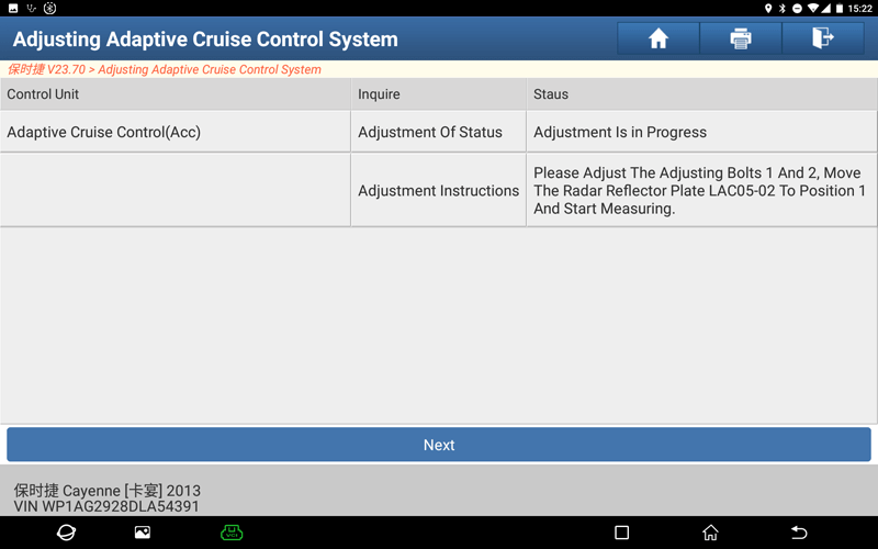
7. Next, please operate according to the Status value of "Adjustment Instructions".
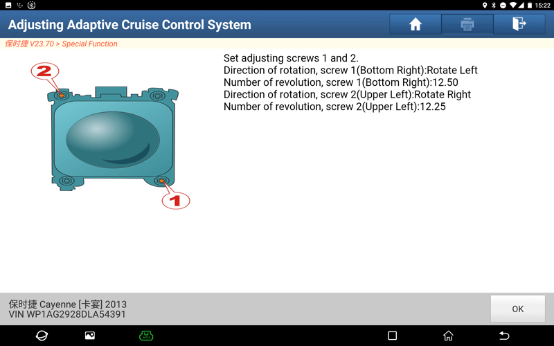
8. Set the adjustment screws 1 and 2, then click "OK".
9. After the adjustment is completed, the following prompt will appear, click "NEXT".
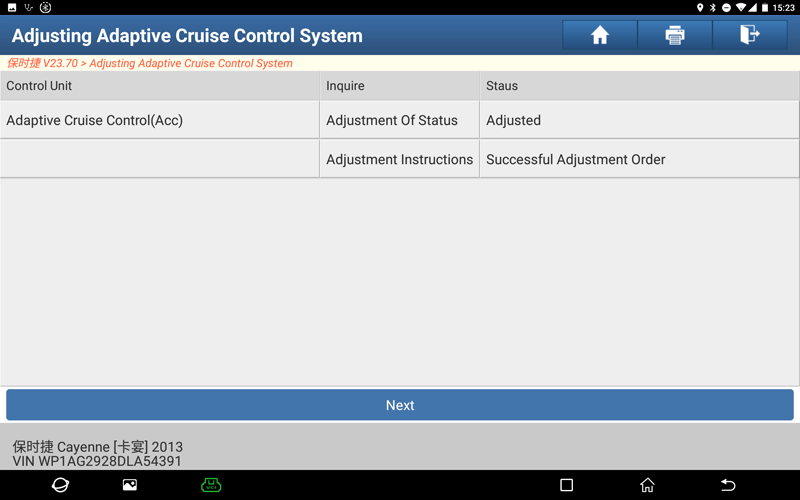
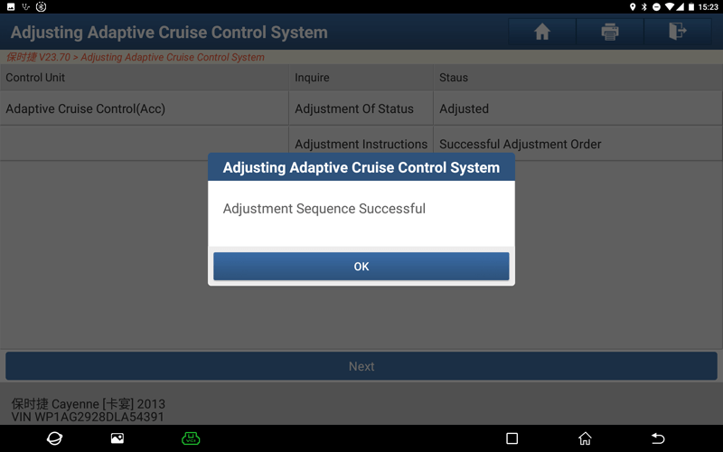
10. It will display that the calibration has been performed successfully, click "OK" to end the function.
Return