


For electric vehicle maintenance, electrical signal detection inside the vehicle is essential. Professional electrical testing equipment can sample electrical signals of electric vehicles for data processing. Finally, it will be displayed in a reasonable way for maintenance personnel to observe and judge the current status and performance of the vehicle. Commonly used electrical testing equipment includes oscilloscopes, multimeters, insulation testing, current clamps, etc.
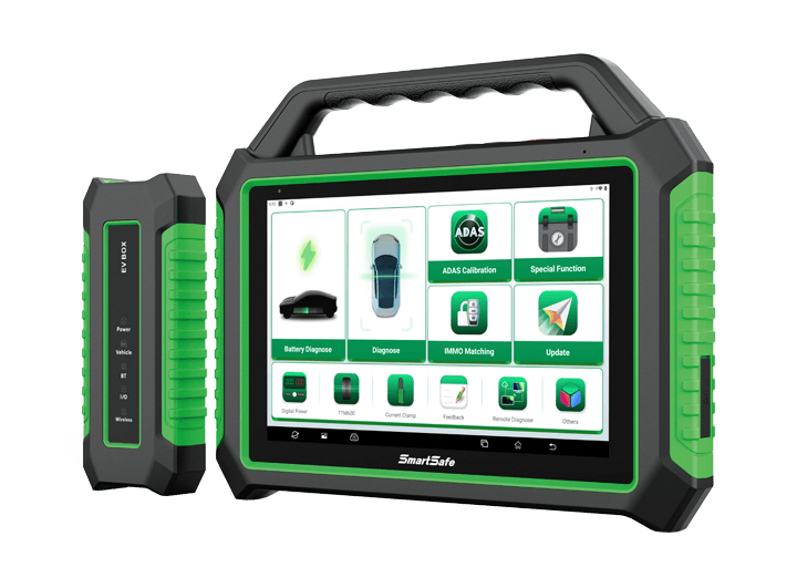
The electric vehicle comprehensive detector iSmartEV P03 launched by SmartSafe integrates electric vehicle battery pack detection and vehicle system detection functions. It also integrates oscilloscope, multimeter, insulation tester and current clamp into one, realizing multi-purpose and multi-functional compatibility. It enables maintenance personnel to get rid of complicated switching of various equipment during the maintenance process of electric vehicles, and quickly determine vehicle faults. At the same time, it is more convenient to manage and carry maintenance tools.
The rate of change of some signals for automotive electronic equipment is very fast, and the change period reaches one-thousandth of a second, while many fault signals are intermittent, sometimes absent. This requires the testing speed of the instrument to be higher than the speed of the fault signal. Usually, the scanning speed of the testing instrument is 5 to 10 times that of the signal to be tested.
An oscilloscope can meet the speed requirement. It can not only quickly capture circuit signals, but also display these waveforms at a slower speed so that maintenance personnel can analyze them while observing. It can also record the signal waveform in the way of storage, and you can come back to observe the fast signal that has occurred, which provides great convenience for analyzing faults. Whether it is a high-speed signal (such as a fuel injector signal) or a low-speed signal (such as a change in throttle position and an oxygen sensor signal), you can use an oscilloscope to observe the waveform to find problems.
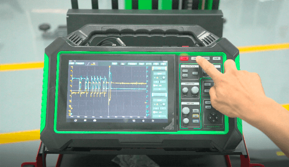
Take the function test vehicle OBDCAN communication line of iSmartEV P03 oscilloscope as an example.
(1) Click "Oscilloscope" on the main interface or click the switch button of oscilloscope function in the upper right corner of the host to enter the oscilloscope module interface.
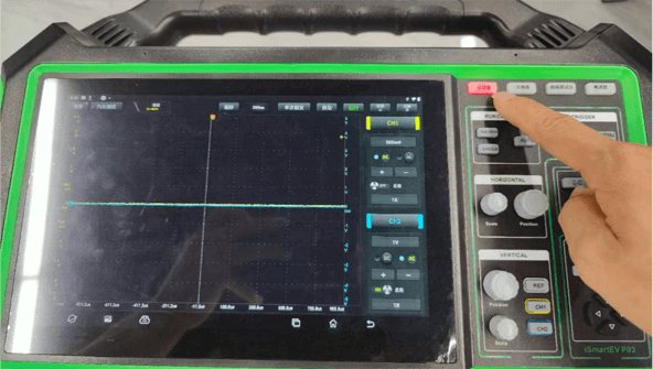
(2) Connect the BNC connector of the oscilloscope test line to channel CH1/CH2. The black connector on the other side is connected to the black needle, and the red connector is connected to the other color needle.
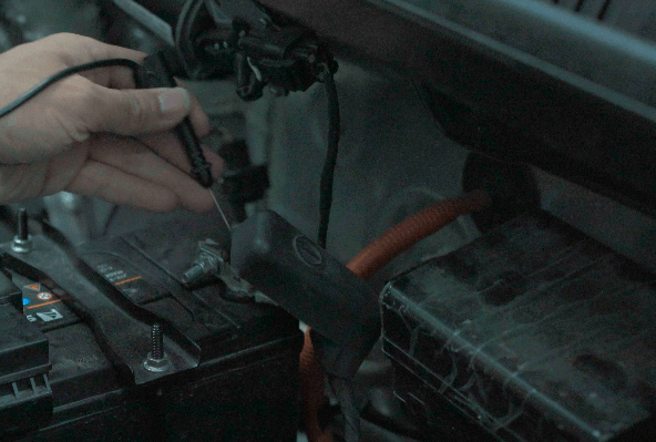
Connect the black needle to the ground port of the vehicle sensor, and the other color needles connected to the red connector to the OBDCAN communication line of the vehicle.
(3) Select the channel, the system has CH1 (channel 1), CH2 (channel 2) and REF (reference channel), and the channel can be selected through the channel button on the right side of the screen. You can also select the target channel through the channel keys in the function key area. Each channel and waveform is marked with a different color (the oscilloscope can display multiple waveforms at the same time, but only one waveform is allowed to be displayed on the top layer first. The channel that is preferentially displayed on the top layer is called the current channel, and it will be marked with →. A channel without this mark is not the current channel).
(4) You can set the horizontal axis unit scale time size. Click "6-Horizontal Setting" to expand the time base value option and select a suitable time base value, or use the "horizontal time base adjustment knob" to adjust to a suitable time base value. If the waveform capture is stopped, the waveform can be enlarged or reduced horizontally by adjusting the horizontal time base.
(5) You can use the channel setting panel to adjust the vertical scale and other settings of the channel. Each channel has a separate setting panel. Each channel can be set individually, or use the "Vertical Voltage Range Adjustment Knob" to adjust the waveform to a suitable voltage range value.
(6) Trigger setting, use the oscilloscope trigger setting function according to the requirement. Click "3-Trigger" to set a certain trigger condition to convert the unstable display content or white screen into a meaningful waveform. When a waveform in the waveform stream meets this condition, the oscilloscope will capture this waveform and other waveforms in real-time. Adjacent parts are displayed on the screen.
(7) Alternatively, you can use Autoset, which is an oscilloscope's Autoset feature that sets the oscilloscope to automatically display waveforms in an optimal manner. Click "Auto", the system will automatically adjust the horizontal and vertical calibration of the oscilloscope, trigger coupling, type, position and other settings, so as to obtain a stable waveform display.
(8) According to the displayed waveform signal, judge whether the vehicle OBDCAN communication line data is normal.
With the development of the automobile industry, more and more electrical equipment is now applied to the car. And when troubleshooting the electrical parts of a car, a multimeter is one of the commonly used automotive electrical repair tools to test voltage, current, and resistance.
Take the iSmartEV P03 multimeter function as an example. This functional module is used to measure voltage, current, resistance, diode and on-off, and it can judge whether the device is good or bad, whether the circuit is complete, etc. by only doing simple measurements.
Voltage test
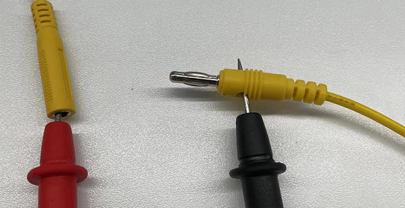
(1) First, prepare the red and black multimeter test pens required for measurement, and find the multimeter measurement port at the top and rear of the host.
(2) Click "Multimeter" on the main interface or click the toggle key of the "Multimeter" function in the upper right corner of the host to enter the interface.
(3) Select "DC voltage" or "AC voltage" and the corresponding range.
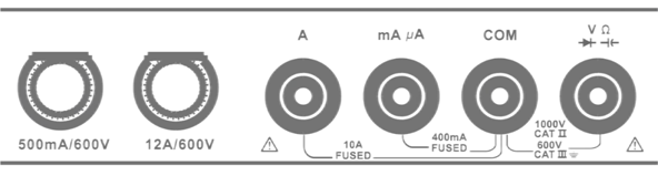
(4) Insert one side of the black multimeter test lead into the "COM" terminal, and insert the other side of the red multimeter test lead into the "V/Ω" terminal (the connection method for measuring DC voltage and AC voltage is the same).
(5) Connect the black test pen to the negative pole of the circuit under test, and connect the test lead of the red test pen to the positive pole of the circuit under test, keep the contact stable, and the test data can be obtained quickly.
Current test
(1) Click "Multimeter" on the main interface or click the toggle key of "Multimeter" function in the upper right corner of the host.
(2) Select "DC Current" or "AC Current" and the corresponding range.
(3) Insert one side of the black multimeter test pen into the "COM" terminal. If the current is greater than 400mA, insert the other side of the red multimeter test pen into the "A" terminal. If measuring a current less than 400mA, insert one side of the red multimeter test lead into the "mA μA" terminal.
(4) Connect the test leads of the black and red test pens to the tested circuit in series to keep the contact stable (the connection method for measuring DC current and AC current is the same).
(5) Click "Start Measurement", and the value will be directly displayed on the screen.
Resistance measurement
(1) Click "Multimeter" on the main interface.
(2) Select "Resistance".
(3) Insert one side of the black multimeter test lead into the "COM" terminal, and insert the other side of the red multimeter test lead into the "V/Ω" terminal.
(4) Connect the test leads of the black and red test pens to the metal parts at both ends of the resistor to keep the contact between the test leads and the resistor stable.
(5) Click "Start Measurement", and the value will be directly displayed on the screen.
Compared with traditional internal combustion engine vehicles, electric vehicles use an electric drive system with a high voltage inside. This will involve overall insulation assessment, especially as the age of the car increases. In the case of system operation such as vibration, temperature and humidity and other environmental changes, it may lead to a decrease in its overall insulation performance, endangering the safety of users and affecting the operation of the car. Therefore, it is very important to test the internal electrical insulation performance of electric vehicles, so professional insulation testing equipment is very important for the detection of insulation performance.
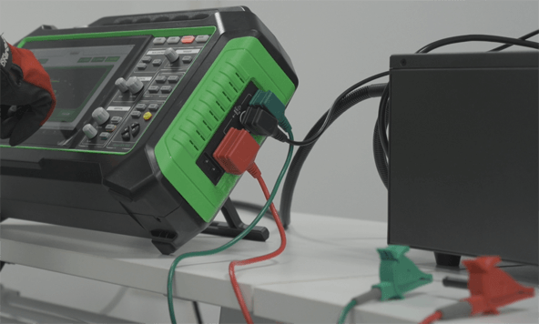
Take the insulation testing function of iSmartEV P03 as an example. This function module is mainly used to measure the insulation resistance of electrical equipment and helps auto maintenance technicians to check and find the risk of short circuits and electric shocks that may be caused by the degradation of the insulation performance of automotive electronic equipment and lines. Automobile maintenance technicians must wear insulating gloves during the insulation test. Operating the insulation test without protection may cause serious electric shock accidents.
Resistance measurement
(1) First, prepare the insulation test wires required for measurement, and find the measurement port of the insulation tester on the right side of the host. Click "Insulation Tester" on the main interface or click the toggle key of "Insulation Tester" function in the upper right corner of the host to enter the interface.
(2) Select "Resistance Measurement" or use the MODE key to switch to "Resistance Measurement" mode.
(3) Insert one side of the red insulated test wire into the "LINE" port, and connect the other side to the conductor of the device under test. Insert one side of the black insulated test wire into the "EARTH" port, and the other side to the ground terminal or the casing of the device under test. Insert one side of the green insulated test lead into the "GUARD" port and the other side to the insulated part of the device under test.
(4) Click to start measurement, and the screen will display the measured voltage value. After the desired value is measured, click "finish measurement" to close the resistance test. There are three measurement methods for resistance measurement: comparative measurement, timing measurement and continuous measurement.
Comparative measurement
(1) Click "Compare Measurement" or click the "COMP" key in the function area.
(2) Click -/+ or the left and right arrow keys in the function area to set the comparison resistance. Click -/+ or the up and down arrow keys in the function area to set the output voltage value, then click "Start Measurement" or press and hold the "TEST" button to start measurement.
(3) After the measurement is completed, the screen will display the measured resistance value. If the measured resistance value is not less than the set comparative resistance value, "GOOD" will be displayed on the upper right corner of the screen. If the measured resistance value is less than the set Compare the resistance value, "NG" will be displayed in the upper right corner of the screen.
(4) Click "Finish Measurement" or click the "TEST" button again to end the measurement.
Timing measurement
(1) Click "Timing Measurement" or switch to "Timing Measurement" through the "TIME" key in the function area.
(2) Click -/+ or the left and right arrow keys in the function area to set the measurement duration. Click -/+ or the up and down arrow keys in the function area to set the output voltage value, and then click "Start Measurement" or long-press the "TEST" key to start measurement.
(3) After the measurement is completed, the screen will display the measured resistance value.
Continuous measurement
(1) Click "Continuous Measurement" or switch to "Continuous Measurement" through the "TIME" key in the function area.
(2) Set the output voltage value through -/+ or the up and down arrow keys in the function area, and then click "Start Measurement" or press and hold the "TEST" button to start measurement.
(3) Click "Finish Measurement" or click the "TEST" button again to end the measurement, and the screen will display the measured resistance value.
When detecting the current of a vehicle, it is often necessary to connect a multimeter in series to the circuit under test, which is likely to cause accidents when connecting lines. As an important tool for automotive electrical testing, current clamps can detect power and grounding without cutting, disconnecting or stripping wires Integrity of the line with minimal intrusiveness.
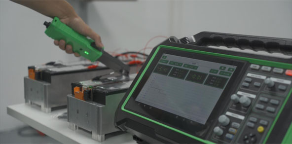
Take the current clamp function of iSmartEV P03 as an example. This functional module needs to be used with new energy current clamp equipment, which can perform AC/DC current tests and DC voltage tests.
(1) Click "Current Clamp" to enter the interface.
(2) Turn the power switch on the current clamp to the "ON" state, and the power indicator light is on.
(3) Click the "Not Connected" button on the screen to start searching for the current clamp. Click the Bluetooth name of the current clamp to be connected (the Bluetooth name is the serial number of the current clamp device) to connect, and the screen will display "Connected" after the connection is successful.
(4) Make sure that the current clamp is not in use. Press the "ZERO" button on the current clamp until the reading on the screen is 0.
(5) Press the trigger to open the pliers, clamp the wire to be measured and click the "Start Measurement" button on the screen to measure.
(6) When measuring the voltage, one side of the current clamp test clip needs to be inserted into the aviation plug of the current clamp. And the other side clamps the positive and negative cables of the power supply to be tested, and then the measurement is performed.
To measure DC leakage: Clamp the positive and negative wires of the DC line simultaneously.
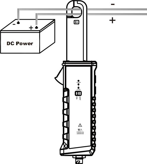
Measure the main line current: only clamp the main line

To measure the leakage current of the ground wire: Clamp the ground wire only.

When measuring AC leakage: Clamp the live wire and neutral wire of the AC line at the same time.
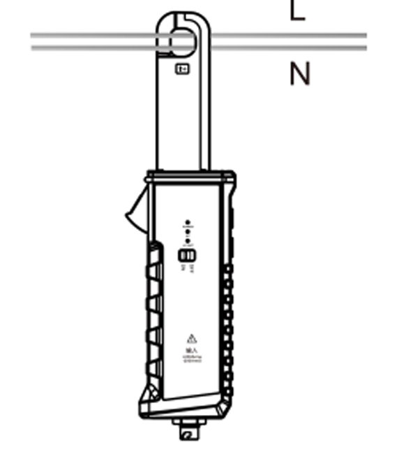
When measuring DC voltage: connect one side of the current clamp test clip to the aviation plug of the current clamp, and the other side respectively clamps the positive and negative cables of the power supply to be tested.

Return


 VIEW All